


Dewatering Screws
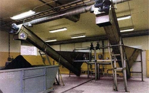
The Dewatering Screw is a simple machine to dewater sand, grit and other matter which can be settled. The working principle is based on a tank and a screw elevator. The elevator transports the waste matter upwards which dewaters the solids to be removed.
Characteristics
- Compact and completely closed
- Axis free screws make bearing in the ‘wet’ part unnecessary
- Minimal turbulence through applied design
- Special design overflow gutter prevents constipation by floating material.
Minimal maintenance
- Directly coupled driven unit with internal bearing
- Little wear of wear plate or wear strip as a result of the low rotation speed
- No need of bearing and sealing under water.
Used material
- Funnel, trough & lids: SS 316L
- Axis free screws: special steel or an alternative Stainless Steel
- Wear plate or wear strips: different qualities, depending on application.
Operation
The residue will be transported upwards through the scew. Above water level, the water flow goes backwards, through which the waste can be transported. The design of the inlet part reduces turbulence to a minimum. A calm flow patron arises. This is necessary for an optimal sedimentation. The axis free screw can be driven continuously as well as discontinuously.

Standard design
The supply funnel and the part of the axis free screw carrier are equipped with demountable lids. The overflow is equipped with an inspection hatch. Across the entire lenght wear strips or wear plates are placed in the trough of the axis free screw carrier. The driven unit is coupled diectly to the assemble plate of the axis free screw.
| Technical data | |||||||
|---|---|---|---|---|---|---|---|
| Type | Flow (l/s) | Water surface(m²) | Content(m³) | IN (ø mm) | OUT(ø mm) | Power(kW) | RPM (min-1) |
| 306-OSS-1-SS | 1-5 | 1.3 | 0.5 | 100 | 150 | 0.25 | 5.0 |
| 306-OSS-2-SS | 5-12 | 2.3 | 1.2 | 100 | 150 | 0.25 | 5.0 |
| 306-OSS-3-SS | 12-20 | 3.0 | 1.8 | 150 | 200 | 0.37 | 4.8 |
| 306-OSS-4-SS | 20-27 | 4.0 | 3.3 | 200 | 250 | 0.75 | 4.6 |
| 306-OSS-5-SS | 27-35 | 5.0 | 4.2 | 200 | 250 | 0.75 | 4.6 |
| Dimensions | |||||||
|---|---|---|---|---|---|---|---|
| Type | A (mm) | B (mm) | C* (mm) | D* (mm) | E* (mm) | L1 (mm) | L2* (mm) |
| * These dimensions are minimum dimensions. Note: when C and L2 increase, A, D and E will also increase |
|||||||
| 306-OSS-1-SS | 2870 | 820 | 1100 | 1150 | 1650 | 2000 | 1000 |
| 306-OSS-2-SS | 3840 | 1170 | 1500 | 1550 | 210 | 3000 | 1000 |
| 306-OSS-3-SS | 4380 | 1420 | 1700 | 1750 | 2350 | 3000 | 1500 |
| 306-OSS-4-SS | 5890 | 1420 | 2150 | 2400 | 3050 | 4000 | 2000 |
| 306-OSS-5-SS | 6290 | 1720 | 2150 | 2550 | 3250 | 4000 | 2500 |